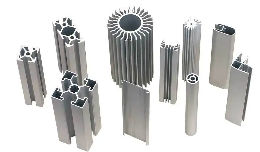
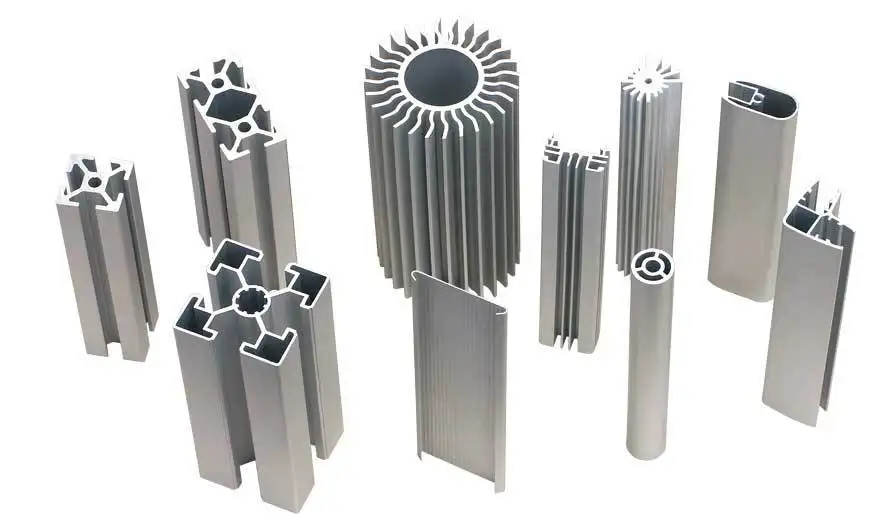
In spite of this, the design of these extrusions has the potential to significantly influence the overall structural soundness of the building, provided that they are not constructed in the appropriate manner. The assembly's cross-sectional area is another significant aspect that needs to be taken into consideration, and this is because this component contributes to the overall weight of the assembly. Extrusions from our 45 mm series are sufficiently adaptable to be used in a wide variety of applications, ranging from range extenders for robots to furniture designed specifically for use in commercial and industrial environments. There are three distinct sizes available for extrusions, and the gap between each of those sizes is indicated in increments of 45 millimeters. The necessary mounting hardware is the same for each of these various dimensions; there is no distinction between them.5 millimeters in height and is 22.5 millimeters across in width. As a result of a 31% decrease in Aluminum Profile area, the 45 x 45 Light-duty offers the best possible equilibrium between the lightweight nature of the Aluminum Profile and the structural rigidity that is based on weight. This is made possible as a direct result of the reduced Aluminum Profile area. Despite the fact that the profile itself does not have a particularly heavy weight, this is still the case.

The fact that 45 x 45 extrusions can be distinguished from those that are considered to be light duty thanks to the presence of the informative label "Light Duty" is the characteristic that can be used to make this distinction. Tabletop aluminum extrusion that measures 5 millimeters by 180 millimeters and is offered in a number of different colors is available to purchase. It is an excellent choice for modular jigs and fixtures because it has t-slots that are evenly spaced apart and a large mounting surface. This is because of its versatility and adaptability. Because of this, it is an outstanding option. This extrusion is capable of supporting robots that generate 1800 Nm of e-stop torque despite the fact that it has a uniform thickness of only 5 mm throughout its entirety. In order to increase the load capacity of the structure, it is strongly suggested that supports be added at regular intervals all the way through the structure. As a consequence of this, the table, once it has been assembled, will have a level surface.
Calculations need to be done in order to determine the safety factor that should be used. For the sake of illustration, if it is anticipated that a structure will collapse when subjected to a force of 1000 N, then a safety factor of two would determine that a maximum allowable load of only 500 N should be applied to it. This is because a safety factor of one would determine that the structure would collapse when subjected to a force of 100 N. This is due to the fact that a safety factor of two takes into account the likelihood that the structure will collapse as a result of the force.
Accuracy and thoroughness are two qualities that are indispensable to the computing process.
the nature of the environment in the regions that are geographically closest to the location of the study.
1. Buckling is one of the most common failure modes, so it is one of the most important aspects to take into consideration when determining the level of durability that a structure possesses
2. Buckling is one of the most important aspects to take into consideration
3. Buckling is a type of deformation that can occur in long vertical beams when those beams are subjected to forces that compress them and cause them to become stretched
4. Buckling can be caused by compression forces
5. As a direct consequence of this deformation, a buckle has appeared
6. The beam has a propensity to bend outwards, which further compromises the structural integrity of the structure, which eventually leads to a sudden failure of the structure
7. Ultimately, this causes the structure to collapse unexpectedly
8. In the end, this brings about the destruction of the structure
9. Third, compute the safety factor by contrasting the maximum load capacity with the force that you intend to apply with the assistance of a free body diagram as a reference
10. You can do this by comparing the maximum load capacity to the force that you intend to apply
11. You'll be able to calculate how much leeway there is for error using this information
Not only can the arrangement of the assembly joints that are used in a design have a significant impact on the rigidity of the design, but it can also have a significant impact on the structural integrity of the design. As a result of this design decision, the structure has become significantly more robust as a direct consequence of the force being transferred directly from the horizontal to the vertical extrusion. Weakness brought on by the friction that develops between the plate and the extrusion whenever they try to transfer their respective amounts of force to one another.
Extremely high tensile strength; the force that is applied is transferred directly to the frame by coming into contact with the vertical extrusions that are present in the profile. The design of the joint that bases its construction on the utilization of reaction forces is the one that is recommended. To put it another way, the strength of the joint is directly proportional to the number of fasteners that were used multiplied by the friction force that was applied by each individual fastener. This was a demonstration of how each individual fastener has the potential to generate 2,100 N of friction. Because of this, the horizontal beam has the ability to withstand a maximum load of 12,600 N (the value for this can be found by multiplying 2,100 N by the number of fasteners, which is six). This can be accomplished by using the formula: 2,100 N multiplied by the number of fasteners, which is six. Our application engineers are typically able to reduce costs by as much as fifteen percent by switching out assembly plates that have six, seven, or eight fasteners for ones that have fewer fasteners. The utilization of assembly plates that contain a reduced number of fasteners is all that is required to bring about this result.
When you combine effective assembly joints with the appropriate extrusion profile, the structural integrity of your assemblies can be improved, allowing you to better meet your customers' needs. You will be able to better satisfy the requirements that have been outlined by your customers as a result of doing this. When it comes to applications that require either high levels of force or pinpoint accuracy, these plates are a fantastic option to use as the base material. The result of your decision will depend on which choice you make among the available options.


